
West Exchange Sidings
Problems
This layout was designed with 4 NX panels, one in each corner. This makes operating the layout hard work, either a lot of walking or a lot of shouting. So it has been decided to go to a single panel operated by JMRI, with and optional front panel to operate the yard for shunting. This will involve replacing all the point controls so that they can be operated by DCC using a separate DCC power district.
The documentation for the current wiring is patchy, out of date, and wrong. Even the tag numbering cannot be relied upon.
Lastly the operation of some of the points using Seep point motors is at best patchy, those near the power supply working better than those at the other end of the layout. This clearly needs to be fixed.
Finally, there has been an issue with bending of D connector pins. This could be due to trying to force 2 male D connectors together, in this case eliminating one set of connectors would help.
Solutions
The 2 short 3ft straight boards at the end of the layout are used for the test track,
so need local control as well as remote DCC control.
The plan is to use the current control switches on the top of the layout,
the single capacitor point CDU's will be replaced by the
MERG design dual capacitor design and a MERG DCC steady state decoder module.
MERG DCC steady state decoder.
Kit 53 firmware in C.
The end boards have a 3 position switch, local control, off, and remote control. The 2 latching push buttons work when in local control. The middle off position puts both crossovers straight to give 4 parallel tracks. The remote control position allows DCC control of the crossovers.
The fiddle yard points, 12 at each end, can be controlled
by 6 MERG pulse decoder modules, controlling 4 points each.
MERG DCC pulsed decoder.
The scenic front of the layout, has 7 points and one end and 8 at the other.
- Initially we will use the same MERG pulse decoder modules as the fiddle yard, with the current Seep point motors, Some points are on the next baseboard, so using the steady state board and CDU's will be necessary.
- These may get changed to Cobalt IP point motors.
Track circuits
For the fiddle yard and front yard its helpful to know which track are occupied. To do this four MERG 2ch DCC only Current Transformer Block Detector DTC2 and one 8ch DCC only Current Transformer Block Detector DTC8 will be used. These operate from 5 volts, and need some way to feed the states back to JMRI. The CBUS CANVINP 16 input module look good, it provides 5 volts out as well. To get the information to a PC we will also need a MERG CBUS USB Interface CANUSB4, probably fitted near to the Lenz command station or fitted in a box and plugged into the CBUS connection.
For the main lines, the signal modules can provide a block occupied signal. This probably means having 3 or 4 CBUS CANVINP modules around the layout.
Power supply
An 18 volt switched mode power supply at about 7 amps should be fine, but we need to test this before the show. All but 2 or 3 points work on 18 volts, these 2 or 3 need some work to fix them.
There is a Lenz command station and a booster, the booster is probably not needed most of the time. The output is a 37 way D connector:
| Pins | Connection |
|---|---|
| 1, 2 | Command station J |
| 5, 6 | AC Transformer 1 winding 1 |
| 8 | Xpressnet L |
| 9 | Xpressnet M |
| 10 | Xpressnet A |
| 11 | Xpressnet B |
| 13, 14 | AC Transformer 1 winding 1 |
| 17, 18 | Booster J |
| 19, 20 | Command station K |
| 23, 24 | AC Transformer 1 winding 2 |
| 25 | C from CS |
| 26 | D from CS |
| 27 | E from CS |
| 29 | D to booster |
| 30 | C to booster |
| 31, 32 | AC Transformer 1 winding 2 |
| 35, 36 | Booster K |
There are 10 fiddle yard tracks, 10 stationary trains at less than 100mA each, is less than 1 Amp. 6 running trains at less than 500mA is another 3 Amps. So the booster is probably not actually needed for running. What is needed is isolated power districts to allow some operation to continue when there is a derailment. We can have a switch so the fiddle yard DCC can be either from the command station or a booster. The front yard may need to be another protected area.
New Wiring
Each baseboard has 2 x 25 way D connectors, connected to a 36 way tag strip. So some connections are on 2 or 3 D pins to carry more current. It looks from the list, as if the first 4 on each connector may have at least 2 pins.
The MERG CDU's take a short pulse of about 500mA to recharge, the pulse decoders only take about 30mA to recharge and 15mA normally. The CobaltIP's are 5mA and 40mA when moving. LED lights may be 10mA each. So after converting all the points to DCC operation, we can convert the power back to dc. This should then make the signal operation easier by having a fixed 0 Volt line. It should be possible to eliminate one of the 25 way D plug and sockets on some boards.
32/0.2 wire will have a resistance of 0.57 ohms for 100 feet, so fine for the DCC to the rails. 16/0.2 will be 1.14 ohms for 100 feet, so fine for 24 Volt dc which will only carry about 1 Amp. 7/0.2 will be 2.6 ohms for 100 feet, so fine for the Xpressnet A and B, or the track section data. The wires to the 20 D connectors and D connectors will increase the resistance a little, 20 x 0.03 = 0.6 ohms, and the DCC pins have 2 or 3 pins in parallel.
The control DCC should come directly from the command station,
and must be protected from any rail connection.
This is done by MERG DCO's(District Cutouts).
Peco insulated frogs can cause shorts as the wheels of some locos pass over them,
54ms cut out delay is faster than the Lenz command station.
Kit 57, MERG DCO.
Tag strip connections
| Tag | Main Connector | Tag | Fiddle Yard Connector | Front Connector | D pins | D pin Colours | Alternate D pin Colours |
|---|---|---|---|---|---|---|---|
| 1 | DCC common, Black 32/0.2 | 19 | DCC common, Black 32/0.2 | DCC common, Black 32/0.2 | 3 | Black+Blue 1, Black 2, Black+Red 3 | Black+Blue 1, Black 2, Black+Red 3 |
| 2 | Main DCC, Red 32/0.2 | 20 | Main DCC, Red 32/0.2 | Main DCC, Red 32/0.2 | 3 or 2 | Red 4, Red+Brown 5, Blue 6 | Red 4, Red+Brown 5 |
| 3 | Fiddle yard DCC, Orange 32/0.2 | 21 | Fiddle yard DCC, Orange 32/0.2 | 2 | Green 7, Yellow 8 | Blue 6, Green 7 | |
| 4 | Signal outer CW | 22 | FY track 1 | Fuel siding | 2 or 3 | Yellow+Red 10 , Yellow+Blue 9 | Yellow 8, Yellow+Red 10, Yellow+Blue 9 |
| 5 | Signal outer CCW | 23 | FY track 2 | Siding 1 | 2 or 1 | White 11, Brown 12 | White 11 |
| 6 | Signal inner CW | 24 | FY track 3 | Carriage 1 | 1 | Purple 13 | Brown 12 |
| 7 | Signal inner CCW | 25 | FY track 4 | Carriage 2 | 1 | Orange 14 | Purple 13 |
| 8 | 26 | FY track 5 | Siding 2 | 1 | Pink 15 | Orange 14 | |
| 9 | 27 | FY track 6 | Siding 3 | 1 | Turquoise 16 | Pink 15 | |
| 10 | 28 | FY track 7 | Point 39 | 1 | Grey 17 | Turquoise 16 | |
| 11 | 29 | FY track 8 | Point 40 | 1 | Red+Blue 18 | Grey 17 | |
| 12 | CBUS Low, Yellow TP 7/0.2 | 30 | FY track 9 | Point 47 | 1 | Green+Red 19 | Red+Blue 18 |
| 13 | CBUS High, Blue TP 7/0.2 | 31 | FY track 10 | 1 | White+Red 20 | Green+Red 19 | |
| 14 | Xpressnet A, White TP 7/0.2 | 32 | 1 | White+Blue 21 | White+Red 20 | ||
| 15 | Xpressnet B, Purple TP 7/0.2 | 33 | 1 | Orange+Blue 22 | White+Blue 21 | ||
| 16 | DCC control, Green 16/0.2 | 34 | 1 | White+Green 23 | Orange+Blue 22 | ||
| 17 | 24 Volts DC, Pink 16/0.2 | 35 | 1 | Yellow+Green 24 | White+Green 23 | ||
| 18 | 0 Volts DC M, Brown 16/0.2 | 36 | 1 or 2 | Orange+Green 25 | Yellow+Green 24, Orange+Green 25 |
The test track oval has the first D pin connections, the fiddle yard and main boards have the alternate connections. These are not compatible so the end fiddle yard and main boards have one of each to convert from one to the other.
Wire colours
There is a main bus of 10 wires running around the layout:- Black 32/0.2, the DCC common. 7/0.2 wire can be used within a basboard.
- Red 32/0.2, the main track DCC, isolated by a MERG District Cutout.
- Orange 32/0.2, the fiddle yard DCC, isolated by a MERG District Cutout. We may need to split this into 2 power districts. Can be powered by a DCC booster.
- Blue and Yellow 7/0.2 twisted pair, MERG CBUS data using Bosch CAN.
- White and purple 7/0.2 twisted pair, Xpressnet A nd B. RS485 data.
- Green 16/0.2 (with Black DCC common), DCC control network direct from the command station.
- Pink and Brown 16/0.2, 24-28 Volt DC supply.
Local 12 volts supply for CBUS modules, Xpressnet L and M, lights etc is provided as necessary by a 12 Volt regulator. The wires are usually red and brown twisted together, red the positive (Xpressnet L) and brown the 0 volts (Xpressnet M).
DCC track sections over a baseboard joint need to use at least 16/0.2 wire.
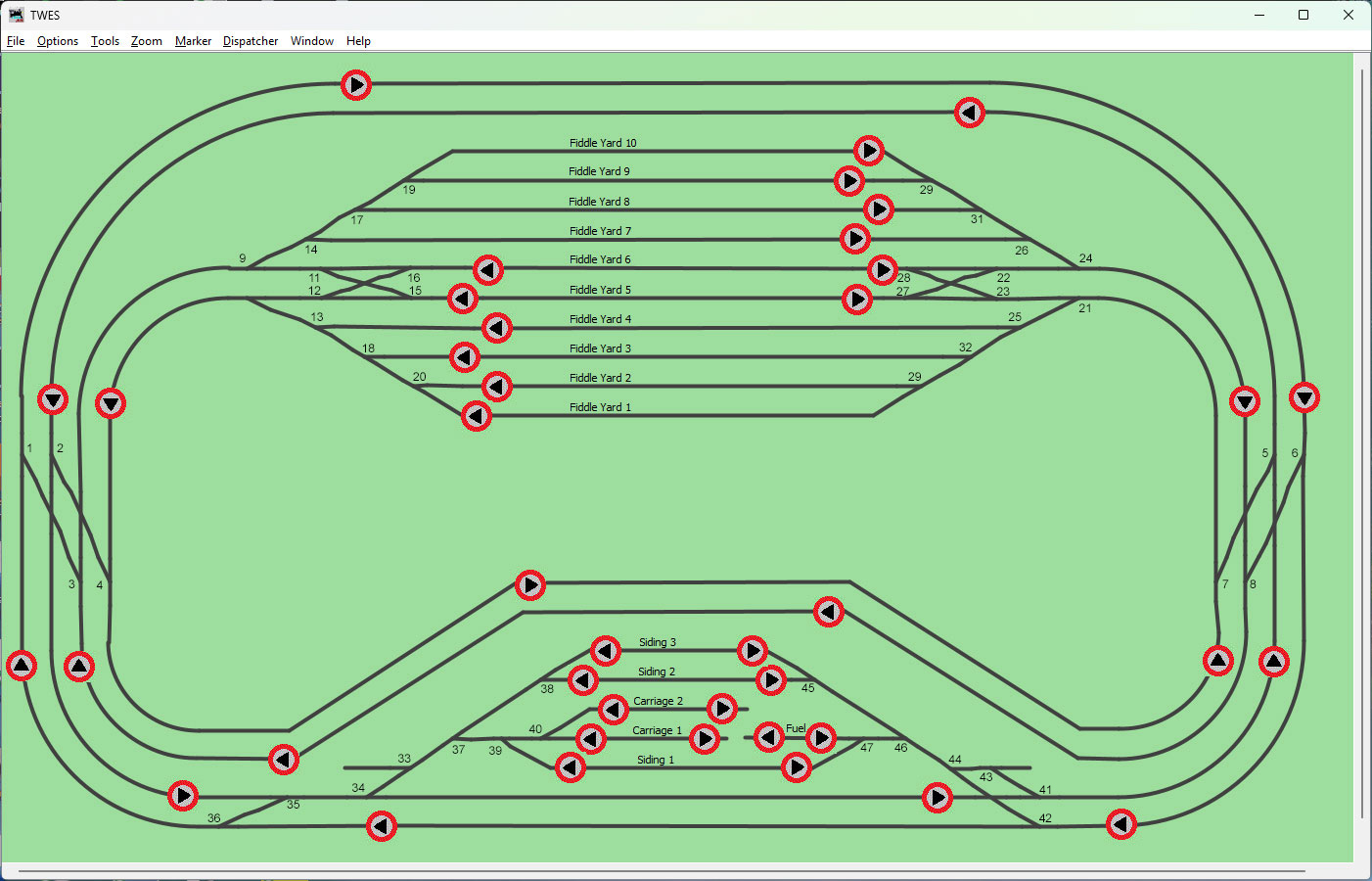
JMRI Screen, with added DCC point addresses.
25 pin D connector wire colours
| Pin | Test Track Colours |
|---|---|
| 1 | Black+Blue |
| 2 | Black |
| 3 | Red+Black |
| 4 | Red |
| 5 | Red+Brown |
| 6 | Blue |
| 7 | Green |
| 8 | Yellow |
| 9 | Yellow+Blue |
| 10 | Yellow+Red |
| 11 | White |
| 12 | Brown |
| 13 | Purple |
| 14 | Orange |
| 15 | Pink |
| 16 | Turquoise |
| 17 | Grey |
| 18 | Red+Blue |
| 19 | Green+Red |
| 20 | White+Red |
| 21 | White+Blue |
| 22 | Orange+Blue |
| 23 | White+Green |
| 24 | Yellow+Green |
| 25 | Orange+Green |