About | Plan | Pictures | Construction | Scenery | Signalling and Control | Layout Team | Exhibitions
Introduction | RPC Hardware | MRCCC Software | Signalling Plan | Wiring Diagrams

Horton's Signalling and Control
Basics
The layout is fully signalled with Roger Murray Colour Light Signals, fully track circuited (for train detection) with MERG FTC modules and has electric control of all mainline points via SEEP motors and MERG CDUs. A Personal Computer (PC) provides the user interface to control the signalling and route setting, together with a comprehensive configurable computer based signalling interlocking.
All route setting is carried out using entry-exit style route setting on the PC. The software also assists in the Cab Control selection via Computer Assisted Cab-Control (CACC), and incorporates a form of Automatic Train Protection (ATP) to prevent trains passing most red signals.
The traction supply is currently conventional DC cab control using six controllers and switched using both rotary switches on a control panel and the CACC relays. Each section is also provided with a section switch, either on the panel, or as a virtual control on the PC.
Digital Command Control (DCC) is now being Used on Horton, together with software changes to support operators when working under DCC. The Lenz system will be used.
The software is the Model Railway Computer Control Centre (MRCCC) software which I have written myself and made available as freeware. Additional Client PCs can connect to allow multiple operators to control or view the layout.
The layout is interfaced to the PC using the Remote Panel Control (RPC) System designed and made available through the Model Electronic Railway Group (MERG)
.System Diagram
The Panel and Relay Rooms connect to the baseboards using 25w 7/0.2 cable. Boards simply connect to the nearest box to reduce cable lengths. The RPC stack is split into three; starting with the main panel housing the RPIC processor (with RS232 link to the MRCCC Server PC), inputs from the main panel to SRI modules, outputs via SRO4 modules to points and signals, FTC track circuit modules and some traction relays, all for those boards fed from the panel.
The Remote Stack Extension system of RSS and RSM modules is used to extend the stack to board F4 where inputs from the fiddle yard panel are read in, and on to the Relay Room with Relays for traction power, FTC track circuits for sections fed from the Relay Room and the SRO outputs to signals and points.
Standard Category 5 network cable and connectors are used to join the RSS and RSM modules to make up the RPC datalink between parts of the stack. The RPC system has been used together with the PC to also provide a transmission system between the panel and the relay room. Section Switches and Cab Control selection switches for the area of the layout fed from the Relay Room are wired to SRI inputs at the Panel. The PC monitors the states of these inputs and drives corresponding SRO4 outputs or DPR relays in the relay room.
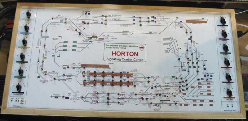
Control Panel
The control panel contains part of the RPC stack, and the switches for traction power. It was constructed from softwood and MDF. The faceplate was produced in Microsoft Visio from the signalling plan, printed in A3 sections on a colour laser printer, laminated, and stuck to an MDF top using double-sided tape before being framed. It was later drilled, fitted with switches and wired.
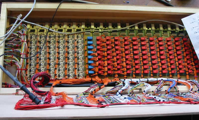
Relay Room
The relay room houses a large part of the RPC stack and feeds the most complex boards at one end of the layout. A large number of CACC relays are located here, and the section switches operate remotely at this end, resulting in more relays. The multi-way cables can be seen terminated on the left hand side and wired to the tagstrips on the inside of the lid.
MRCCC Screenshot
The screenshot below shows a typical view of the MRCCC software in Test Mode. Trains are shown in red, with routes set being white.